
How to convert the Skywatcher SupaTrak mount into a computer controlled GOTO mount
Perhaps late June was the wrong time of year to finally fulfill my boyhood dream of buying a telescope. Certainly the fact that it doesn’t get dark until 11pm isn’t a good start for observing when you get up early anyway, then the weather has hardly been helpful…
So to keep myself from getting bored through the long, light, evenings of summer I started wondering whether you could computer control the SupaTrak mount – after all, it looks just like the Celestron SLT mount and Celestron are owned by Synta *and* engineers love to re-use things that work. I found a bunch of very interesting information at Matthias Bopp’s site (here, look in the Astro Downloads section), particularly on how the Nexstar mounts worked and the handset communications protocol worked.
In actual fact, I found out that nothing is quite the same as the Nexstar mount – the pinout on the handset cable is different, the communications protocol is different and the TTL to RS232 circuit based on a couple of transistors didn’t work with any of my serial ports, but all of those problems can be overcome.
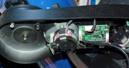
Inside the SupaTrak Mount
The mount contains two motor assemblies (altitude and azimuth) and a motor controller circuit board. The main ICs on the circuit board are a pair of PIC16F78 microprocessors (one controlling each axis). The black cable running out of the image on the bottom right goes to the data and power sockets on the mount cover.
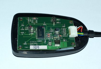
The handset contains a single PIC16F73 microprocessor which monitors the button presses and sends commands to the mount.
The Interface Circuit
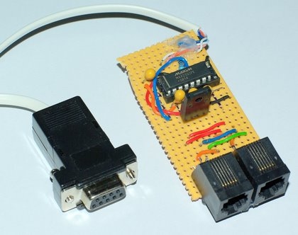
Here’s the circuit I put together to interface from the scope handset<->mount wiring to RS232. It’s not really a neat solution to the problem as it evolved gradually as I learnt more about how the system worked. The 2 RJ12 sockets at the front are wired in parallel, so you can plug the handset into one and an RJ12-RJ12 crossover cable between the other and the mount. This setup allowed me to snoop on the handset<->mount communications, but isn’t necessary for simple computer control.
Building a system using RJ12 sockets allows you to avoid modifying your mount or handcontroller in any way, unfortunately it adds to the cost of the project – the only UK supplier I could find for the sockets and the appropriate cable is Farnell who have a minimum order value of £20 + VAT. Additionally you need RJ12 (6P6C plugs, which are more widely available and an appropriate crimp tool (or a good deal of patience to manually crimp the plugs onto the cable. It’s also worth noting that the pins of the RJ12 sockets are on a 1/20th inch spacing, so don’t work nicely with prototyping board. I ended up bending up alternate pins to sit above the board (not visible in the picture above).

Here is a schematic diagram for the interface circuit (click to see it full size). I have drawn this from my own circuit and cross checked against the wiring list given in the PDF instructions, but I would still advise implementors to check that the schematic and the wiring list match up as they work (just in case I have missed something). Note that I forgot to put capacitor C5 on my circuit with no apparent ill effects.
Wiring Guidelines
- Get the cable you intend to connect to the mount/handset attached to your circuit board and connect to the 7805 voltage regulator.Do not connect to the mount or handset at this stage. Make sure that this cable has 4 cores, since I suspect we may have to do something with the flow control line at a later date.
- At all stages before powering up, check for unexpected shorts between adjacent tracks/wires.
- Apply 12V to the +12V and Ground lines of your handset wire and check you have +12V between the +12V line and ground and +5V between the voltage regulator output and ground. You can easily get 12V from your batter pack, from the terminals that the power lead is connected to.
- Wire in the MAX232 chip (power and capacitors only, don’t connect any data lines yet). I prefer to use a socket for wiring in chips rather than soldering the chip directly to the board
- Once again check for connectivity (both that your intended connections are made and that you have no shorts between adjacent pins on the chip for instance)
- Apply power again and test for +5V between pins 16 and 15, ~ +10V between pins 2 and 15 and ~ -10V between pins 6 and 15. This shows that the charge pump circuitry of the chip is correctly generating RS232 levels.
- Connect up the data line from the mount/handset to pin 11 and pin 12 via the 1K resistor.
- Check for shorts again. Check that you have made the connections shown
- Now connect the other end of your cable into the mount/handset by your chosen method.
- Moment of truth #1 – if you can connect your handset and your control circuit at the same time, do so and apply power to the mount. If all is well the handset should initialize normally (with the Guide/1 button illuminated) and you should be able to move the mount using the buttons. If not (handset buttons flash), disconnect and check everything.
- Now wire in the RS232 connections to the circuit, once again check for unexpected short circuits.
- Connect up the mount again and plug your RS232 lead into a COM port on your PC, start HyperTerminal (usually in Start->Accessories->Communication) and set it up for the COM port you have plugged into, 9600 baud, 8 data bits, no parity, one stop bit, no flow control. You also need to go into File->Properties->Settings->ASCII Setup and check the box ‘Append Line Feeds to Incoming Line Ends’ or everything will appear on one line
- Plug in the handset too and apply power to the mount – you should see both sides of the communication between handset and mount – starting ‘:F1’, ‘=’, ‘:F2’, ‘=’ etc.
- In HyperTerminal, type ‘:F1’ and press <Enter> – you should see a response of ‘=’ from the mount – this means you have got two way RS232 communications working. If not, go back and check everything again!
How To Connect To The Mount/Handset Wiring
I chose to wire two RJ12 sockets in parallel and create an RJ12 crossover cable – the crossover cable is run between any one of the sockets and the mount, and the handset plugged into the other socket. In this way I haven’t had to physically modify either my handset or mount, but it is perhaps the most expensive way to connect up – you need RJ12 plugs and sockets, a crimping tool and suitable 6 way flat cable – smaller suppliers won’t stock all of these.
I would suggest the following possible alternatives:
- Connect via a single RJ12 plug which plugs into the mount instead of the handset – no modifications again, no need to get your hands on RJ12 sockets but you still need a plug and the appropriate cable, also you can’t plug in both the handset and the computer interface.
- Cut the handset cable and connect into the middle of the cut cable – perhaps the cheapest option and will allow both the computer interface and the handset to connect at once, but obviously voids your warranty and looks pretty nasty.
- Open up the handset and connect to the internal wiring – the contacts are pretty small in their and you would have to modify the handset to get your wiring out, but tidier than cutting the cable
- Open up the mount and connect to the internal wiring – much more room in here than in the handset – possibly even enough to tuck the interface circuit away. You’ll need to modify the mount case to get the wiring out though.
Electrical Interface
The communications between the mount and the handset is a bit odd – using 2 wires for power (+12V and ground) and 2 for data. One of the data wires is bidirectional signal (half duplex, 9600 baud 8N1), while the other is flow control. I presume that the sending component pulls the flow control wire low to indicate that they are sending and the other component will not send until it is released again. I didn’t bother wiring up a connection to the flow control line in my final circuit, since PC<->mount communications seem to work well without it.
More Detailed Information
I’ve written up a lot more detailed information about the scope/handset communications and how to interface to it – you can find it in this document : SupaTrakMountHacking.pdf
Erratum to Communications ProtocolI clearly haven’t got a full understanding of the ratio parameter of the ‘G’ command – in my original tests it seemed that a goto command used a value of 4 for this parameter, but later tests showed a 0 being sent. There is also what looks like a bug and workaround related to this in the handset/mount communications. After a goto command over a fairly long distance (which uses the top motor speed), movement commands for intermediate speeds (i.e. 32x sidereal in normal ratio) are misinterpreted by the mount which moves about 10x faster than expected. The only workaround for this I have found so far is to query the axis for its sidereal rate (D), start it moving (L, I, G, J), stop it again (L) and repeat. Maybe if I understood the G command better, this would make sense.
Driver Software
I have written an ASCOM driver for the mount, which now seems to work at least to some degree. Read more about it here. The source code is also available for those who want to play or who run systems that don’t support ASCOM.
Disclaimer
I have no connection with SkyWatcher, Synta or any of the other companies mentioned here. All the information has been discovered by my own experimentation. I haven’t managed to damage my mount or handset while doing this experimentation, but that doesn’t mean that yours is guarenteed safe. In particular if you mess up the interface circuit, you could damage something.
All software, circuit diagrams and other information provided here comes with no warranty, either express or implied of suitability for any purpose. The author disclaims all liability of any kind for any damage caused by the use of this information. If you break something, you get to keep both halves…